Research 2nd year: Difference between revisions
No edit summary |
No edit summary |
||
| Line 1: | Line 1: | ||
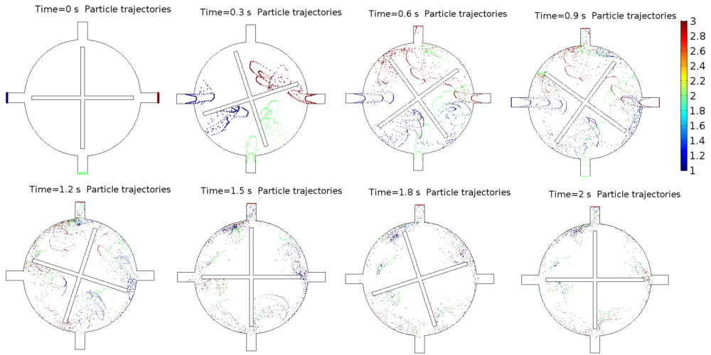
The idea for further conducted simulations begins with the introducing convection phenomenon in the slurry chambers. Instead of introducing a new physics to our previous modeled geometry we started a new model of micro-mixer with inlets and outlets for particles to move with user fixed density. This is the first step to which will help us to utilize the fluid dynamics in flow capacitor model. Below in the figure 1 is the geometry shown for one micro-mixer and the velocity variation of particles. In figure 2 is th particles path in the mixer, starting from inlet for next 2sec. | The idea for further conducted simulations begins with the introducing convection phenomenon in the slurry chambers. Instead of introducing a new physics to our previous modeled geometry we started a new model of micro-mixer with inlets and outlets for particles to move with user fixed density. This is the first step to which will help us to utilize the fluid dynamics in flow capacitor model. Below in the figure 1 is the geometry shown for one micro-mixer and the velocity variation of particles. In figure 2 is th particles path in the mixer, starting from inlet for next 2sec. | ||
[[File:Untitled.png|center | [[File:Untitled.png|center|400dpi]] | ||
[[File:Untitled1.png|center|400dpi]] | [[File:Untitled1.png|center|400dpi]] | ||
In start we used the micro-mixer model which is assumed as a slurry chamber, and step wise introduced another micro-mixer for second slurry chamber. The first problem that arise is the coupling of both chambers in a way that both mixers should be moving but because of some overlapped boundary conditions only one mixers was moving. | In start we used the micro-mixer model which is assumed as a slurry chamber, and step wise introduced another micro-mixer for second slurry chamber. The first problem that arise is the coupling of both chambers in a way that both mixers should be moving but because of some overlapped boundary conditions only one mixers was moving. After careful analysis of two coupled mixers and introducing the new boundary conditions we are successful in get running both mixers together. | ||
Revision as of 19:22, 3 November 2017
The idea for further conducted simulations begins with the introducing convection phenomenon in the slurry chambers. Instead of introducing a new physics to our previous modeled geometry we started a new model of micro-mixer with inlets and outlets for particles to move with user fixed density. This is the first step to which will help us to utilize the fluid dynamics in flow capacitor model. Below in the figure 1 is the geometry shown for one micro-mixer and the velocity variation of particles. In figure 2 is th particles path in the mixer, starting from inlet for next 2sec.
In start we used the micro-mixer model which is assumed as a slurry chamber, and step wise introduced another micro-mixer for second slurry chamber. The first problem that arise is the coupling of both chambers in a way that both mixers should be moving but because of some overlapped boundary conditions only one mixers was moving. After careful analysis of two coupled mixers and introducing the new boundary conditions we are successful in get running both mixers together.

