09/5/1: Difference between revisions
(New page: == Preparation of 3-layer actuators containing CNT-s, EMIBF<sub>4</sub>, PVDF-HFP == Preparation of actuator electrode layers: *'''CNT'''(ID-PO356) 50.04 mg *'''EMIBF<sub>4</sub>''' (Ald...) |
No edit summary |
||
| (20 intermediate revisions by the same user not shown) | |||
| Line 2: | Line 2: | ||
Preparation of actuator electrode layers: | Preparation of actuator electrode layers: | ||
[[Image:3-Layer actuator.jpg|right|300px|]] | |||
*'''CNT'''(ID-PO356) 50.04 mg | *'''CNT'''(ID-PO356) 50.04 mg | ||
| Line 9: | Line 10: | ||
The electrode layer was fabricated by casting 1.6 ml of the electrolyte solution in the Teflon mold (an area of 2.5cm×2.5cm) and evaporating the solvent, perfectly. The thickness of the obtained electrode film was | The electrode layer was fabricated by casting 1.6 ml of the electrolyte solution in the Teflon mold (an area of 2.5cm×2.5cm) and evaporating the solvent, perfectly. The thickness of the obtained electrode film was 50–60 μm. | ||
| Line 20: | Line 21: | ||
The gel electrolyte layers were fabricated by casting 0.3 ml of the solution to the Tefon mold (an area of 2.5cm×2.5 cm) and evaporating the solvent perfectly. The thickness of the obtained gel electrolyte film was 15-18 | The gel electrolyte layers were fabricated by casting 0.3 ml of the solution to the Tefon mold (an area of 2.5cm×2.5 cm) and evaporating the solvent perfectly. The thickness of the obtained gel electrolyte film was 15-18 μm. An actuator film was fabricated by hot-pressing the electrode and electrolyte layers which have the same internal IL. The thickness of the actuator film was 100-110 μm, which are smaller than the sum of those of two electrode and one electrolyte layers, since the thickness of each layer decreases by being hotpressed | ||
== Actuator performance analysis == | |||
Ionic conductivity κ of electrolyte layer was calculated from data obtained from electrochemical impedance spectroscopy (EIS) measurements. R value was determined from Nyquist`s plot. | |||
<math>\kappa=\frac{d \left (cm\right )}{S \left (cm^2 \right ) \times R \left ( \Omega \right)}\, \qquad \left (1\right )</math> | |||
In formula (1) '''d''' is a thickness of the electolyte layer, '''S''' is an area of circular shaped elctrolyte layer film and '''R''' is a resistance of electrolyte film obtained from Z ′ Z ″ -plots | |||
Results: <math>\kappa_{231 \ \mu m}=4.3 \ \mbox{mScm}^{-1} </math> and <math>\kappa_{228 \ \mu m}=3.2 \ \mbox{mScm}^{-1} </math> | |||
---- | |||
Gravimetric capacitance was calculated from cyclic voltammetry measurements. Cyclic voltammograms of actuator at different sweep rates between voltage range ±0.5 V and ±1 V. | |||
[[Image:I,E at 0,5 V.jpg|centre|frame|'''Cyclic voltammograms of actuator at sweep rates 100, 10 and 1 mV/s between voltage range ±0.5 V''']] | |||
[[Image:Gravimetric_Capacitance.jpg|centre|frame|'''Dependence of the gravimetric capacitance of the actuator at different sweep rate values''']] | |||
[[Image:Strain vs Freq.jpg|500 px|centre]] | |||
The frequency dependence of the generated strain shown in this figure is attributed to the electrochemical kinetics (a double-layer charging kinetic model). At low frequencies of the applied rectangle voltage, the carbon nanotube dispersed in the electrode layer is fully charged and actuator exhits maximal strain. On the contrary, at higher frequencies, there is not enough time for the dispersed SWNTto be fully charged and strain generated by the actuator is reduced remarkably. Hence, the amplitude of the accumulated charge decreases with the increase in the frequency and its phase is delayed to the applied voltage. | |||
---- | |||
[[Image:Schema.jpg|400 px]] [[Image:Elektronjuhtivuse pilt.jpg|300 px]] | |||
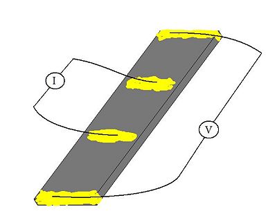
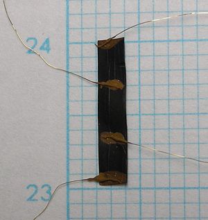
The electrode conductivity was measured by four-probe DC current method. For the electrode sheet 2mm × 10mm (right picture) the coductivity value was estimeted <math> 1.44 \ Scm^{-1} </math>. | |||
==Synthesis of Actuator with Asymmetrical behavior == | |||
[[Image:Asymmetriline-EMIBF4-OMIBF4_membraan_50_50_Joonis3.jpg|400 px]] [[Image:Asymmetriline-EMIBF4-OMIBF4_membraan_50_50_Joonis4.jpg | 480 px]] | |||
Latest revision as of 08:49, 5 June 2009
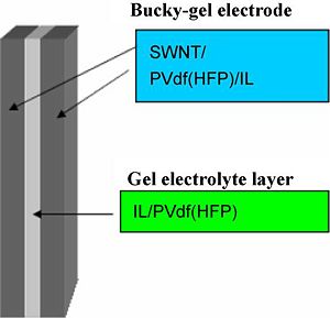
Preparation of 3-layer actuators containing CNT-s, EMIBF4, PVDF-HFP
Preparation of actuator electrode layers:
- CNT(ID-PO356) 50.04 mg
- EMIBF4 (Aldrich) 124.5 mg
- PVDF-HFP (Kynar 2801) 50.1 mg
- DMAc ~(4 mL + 5 mL)
The electrode layer was fabricated by casting 1.6 ml of the electrolyte solution in the Teflon mold (an area of 2.5cm×2.5cm) and evaporating the solvent, perfectly. The thickness of the obtained electrode film was 50–60 μm.
Preparation of actuator electrode layers:
- EMIBF4 (Aldrich) 202 mg
- PVDF-HFP (Kynar 2801) 204,3 mg
- PC 497 mg
- MP 2 mL
The gel electrolyte layers were fabricated by casting 0.3 ml of the solution to the Tefon mold (an area of 2.5cm×2.5 cm) and evaporating the solvent perfectly. The thickness of the obtained gel electrolyte film was 15-18 μm. An actuator film was fabricated by hot-pressing the electrode and electrolyte layers which have the same internal IL. The thickness of the actuator film was 100-110 μm, which are smaller than the sum of those of two electrode and one electrolyte layers, since the thickness of each layer decreases by being hotpressed
Actuator performance analysis
Ionic conductivity κ of electrolyte layer was calculated from data obtained from electrochemical impedance spectroscopy (EIS) measurements. R value was determined from Nyquist`s plot.
[math]\kappa=\frac{d \left (cm\right )}{S \left (cm^2 \right ) \times R \left ( \Omega \right)}\, \qquad \left (1\right )[/math]
In formula (1) d is a thickness of the electolyte layer, S is an area of circular shaped elctrolyte layer film and R is a resistance of electrolyte film obtained from Z ′ Z ″ -plots
Results: [math]\kappa_{231 \ \mu m}=4.3 \ \mbox{mScm}^{-1} [/math] and [math]\kappa_{228 \ \mu m}=3.2 \ \mbox{mScm}^{-1} [/math]
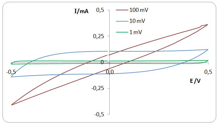
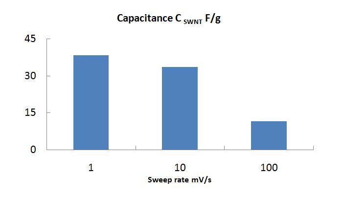
Gravimetric capacitance was calculated from cyclic voltammetry measurements. Cyclic voltammograms of actuator at different sweep rates between voltage range ±0.5 V and ±1 V.
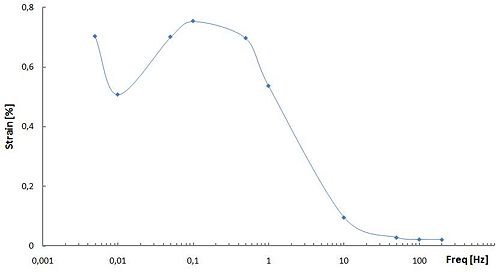
The frequency dependence of the generated strain shown in this figure is attributed to the electrochemical kinetics (a double-layer charging kinetic model). At low frequencies of the applied rectangle voltage, the carbon nanotube dispersed in the electrode layer is fully charged and actuator exhits maximal strain. On the contrary, at higher frequencies, there is not enough time for the dispersed SWNTto be fully charged and strain generated by the actuator is reduced remarkably. Hence, the amplitude of the accumulated charge decreases with the increase in the frequency and its phase is delayed to the applied voltage.
The electrode conductivity was measured by four-probe DC current method. For the electrode sheet 2mm × 10mm (right picture) the coductivity value was estimeted [math] 1.44 \ Scm^{-1} [/math].
