EchemDID: Difference between revisions
No edit summary |
|||
| (47 intermediate revisions by the same user not shown) | |||
| Line 43: | Line 43: | ||
'''Triangular prism in MD''' | '''Triangular prism in MD''' | ||
Constructed a right triangular prism with a side length of 70 angstrom. The width in the periodic direction was 35 angstroms. The surface on the diagonal was the [110] surface. The counter-electrode was constructed as a single point and set outside the cutoff of the QeQ , to mimic a bias voltage on the system with respect to infinity. An adatom was placed in the middle of the prism to allow to study the effects on the adatom within the same system, as it did not change the charge distribution significantly. voltage of 20V was applied to the prism. | Constructed a right triangular prism with a side length of 70 angstrom. The width in the periodic direction was 35 angstroms. The surface on the diagonal was the [110] surface. The counter-electrode was constructed as a single point and set outside the cutoff of the QeQ , to mimic a bias voltage on the system with respect to infinity. An adatom was placed in the middle of the prism to allow to study the effects on the adatom within the same system, as it did not change the charge distribution significantly. voltage of 20V was applied to the prism. | ||
'''Triangular prism in comsol''' | '''Triangular prism in comsol''' | ||
Constructed a prism in comsol to match the dimensions of the MD system. To mimic the potential with respect to infinity, a large cylinder(100x the size of the prism) was created. Voltage of 20V was applied between the prism and the cylinder. | Constructed a prism in comsol to match the dimensions of the MD system. To mimic the potential with respect to infinity, a large cylinder(100x the size of the prism) was created. Voltage of 20V was applied between the prism and the cylinder. | ||
[[ Image:prism_side_md.png |250px|left]] | |||
[[File:mdfem_compare.png|800px]] | |||
[[ | ====Electric field comparison ==== | ||
The electric field values in MD were calculated in two ways: first way: <math display="inline">E=F/q</math>, where ''F'' is the electrostatic force acting on a surface atom and ''q'' is its charge. The other method is to look as the electrostatic force as a primary output, and the electric field as calculated: | |||
<math display="inline">E=\sqrt(2f/(s \varepsilon_0))</math>, where ''s'' is the mean atomic surface area, ''f'' is the electrostatic force acting on a particular atom. The electric field values in FEM in the middle of the prism, far from the edges were around <math display="inline">0.9 GV/m </math> . The values in MD, calcuated from the first method were around <math display="inline">3.6 GV/m</math>. The value calculated from the second method was display="inline">1.06 GV/m</math>, which is much closer to the field calculated by FEM. '''Conclusion:''' The electric field values calculated from the forces and mean areas give predictions much closer to the FEM values. The downside of this method is that in the case of deformed geometries, it might be hard to define a sensible mean surface area. | |||
==== Electric field gradient comparison ==== | |||
[[File:Mdfem compare line.png|800px]] | |||
We can see that the distributions, while different, follow similar patterns. The most notable difference is probably the strong electrostatic shielding the edge atoms provide in the MD case to the neighboring atoms. The main source of uncertainty is probably the surface area value. | |||
=== Triangular protrusion === | |||
In both MD and FEM cases, the counterelectrode was placed unphysically close. This was done to obtain a noticeable gradient in the MD case, and be able to compare with FEM. | |||
[[File:mdfem_compare_wedge.png|800px]] | |||
=== Tilted planes === | |||
System in MD consists of two planes at an angle with respect to each other. Additionally, there is an adatom on the bottom plate at various positions. Tests showed that the greatest effect on the adatom happens when the adatom is near the edge, thus I will focus on that geometry. FEM calculations were conducted as to mimic the geometry and the dimensions of the MD system closely and as the adatom described as a hemisphere. | |||
[[File:Mdfem compare tiltplane.png|800px]] | |||
==== Electric field gradient comparisons ==== | |||
[[File:Efieldmd.png|500px|left]] | |||
[[File:Tiltplane comsol line.png|500px|center]]<br /> | |||
==== Echemdid simulation - pyramid - adatoms ==== | |||
Geometry :ca 80k atoms, truncated {111} pyramid in the middle, surrounded by adatoms. Simulation setup: cg minimization 1e-8 tolerance, 700 steps, box was allowed to relax. Velocity created at 10K, short equilibration with langevin thermostat, N-H barostat (fix nph). Then 10k steps raising temperature from 10K to 600K with langevin thermostat, while barostatting the box. <br /> The results - stable system at 600K with 0 pressure in the x and y directions. Langevin thermostat performed better than the NH one, as that one was unstable for some reason. | |||
Latest revision as of 16:25, 27 February 2019
Testing with variable cut-offs:
/home/kristian/sshfs/rocket/echemtest/validation/forces_capa/test_cutoff
The default cut-off for the Coulombic interaction for the Qeq scheme used in EchemDID is 15 Å. Did tests with 20, 30,40.... 100 Å with the distance between plates being 18 Å. Found out that at higher cut-off values, the scheme breaks down entirely. The force and charge distributions become increasingly unphysical. Probably better to use the pre-determined cut-off value parametrized for the force field, even though this might cause the known problems.
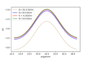
Potential landscapes for different electric fields
Did tests with different electric fields by moving a test atom on 100 surface by one lattice constant. We can see, that greater the electric field, lower the potential energy of an adatom.
16.10 Minimization and dynamics of adatom; general review QeQ+Efield papers.
Ran the minimization of an adatom on the tiltsurface. It worked, but does not give anything that interesting. The forces go to 0 if the tolerance is low enough, as should be. At least it does not crash, meaning it is possbile to simulate such a system. Single atom temperature has no meaning - which should be well understood. Also thats the reason it is not possible or worthwhile to run dynamics with only the adatom unfrozen. Tried to run the whole tiltplane system at 300 K, which gave bogus results. Furthermore, more sensitive tests should be run only on minimized systems. Read https://doi.org/10.1016/j.ijsolstr.2007.09.010. It seems, that the electric field gradient is the driving force, although they look from contiinum-analytical perspective. Also it seems from their arguments, that the electric field gradient runs the diffusion anyways, without the necessary parallel components(dipoles)
Found several other methods which include the effect of the electric field. For example: https://doi.org/10.1063/1.5029877 Says, that they got rid of the cut-off problem. Hard to understand how from the paper, seems just a bit modified $\chi_{effective} -V/2$. They also have a fully filled system(no vacuum)
Also, the Van Duin paper for Ni/H2O interface supports the $\chi_i\rightarrow \chi_i + \mathbf{r_i}\cdot \mathbf{E}$ formulation. Although they have a tiny slab and fully filled, so the cut-off problem might not arise as heavily. They introduced additional force q*E also. This also makes sense (outside the cut-off the forces from the distant plane/point are not taken into account)
The main question: in the case of p-plate cap, is the effect of the electric field to change: $$\chi_i \rightarrow \chi_i \pm \frac{V}{2}$$
Or $$\chi_i \rightarrow \chi_i \pm \mathbf{r_i} \cdot \mathbf{E}$$
Where $V$ is the external potential difference, Both cannot be right at the same time. Or do they correspond to different physical models? If so, to which models they correspond? How do they interact with the finite cut-off? After all, the cut-off is there to make problems computationally feasible..
Comparisons of EchemDID and FEM
Did 3 comparisons with different geometries, some with adatoms, some without.
Triangular prism
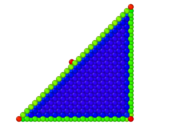
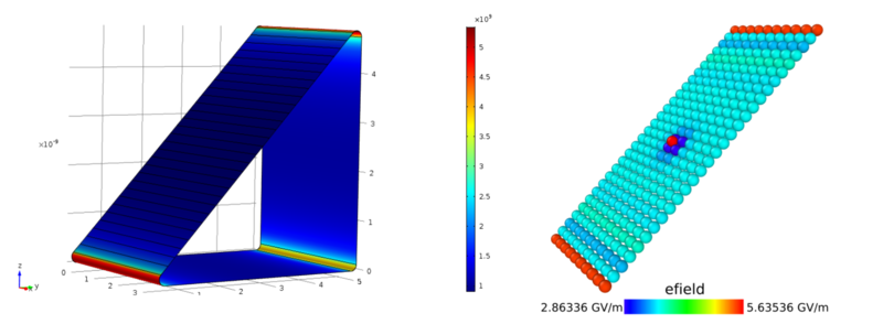
Triangular prism in MD Constructed a right triangular prism with a side length of 70 angstrom. The width in the periodic direction was 35 angstroms. The surface on the diagonal was the [110] surface. The counter-electrode was constructed as a single point and set outside the cutoff of the QeQ , to mimic a bias voltage on the system with respect to infinity. An adatom was placed in the middle of the prism to allow to study the effects on the adatom within the same system, as it did not change the charge distribution significantly. voltage of 20V was applied to the prism.
Triangular prism in comsol Constructed a prism in comsol to match the dimensions of the MD system. To mimic the potential with respect to infinity, a large cylinder(100x the size of the prism) was created. Voltage of 20V was applied between the prism and the cylinder.
Electric field comparison
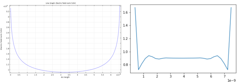
The electric field values in MD were calculated in two ways: first way: [math]E=F/q[/math], where F is the electrostatic force acting on a surface atom and q is its charge. The other method is to look as the electrostatic force as a primary output, and the electric field as calculated: [math]E=\sqrt(2f/(s \varepsilon_0))[/math], where s is the mean atomic surface area, f is the electrostatic force acting on a particular atom. The electric field values in FEM in the middle of the prism, far from the edges were around [math]0.9 GV/m [/math] . The values in MD, calcuated from the first method were around [math]3.6 GV/m[/math]. The value calculated from the second method was display="inline">1.06 GV/m</math>, which is much closer to the field calculated by FEM. Conclusion: The electric field values calculated from the forces and mean areas give predictions much closer to the FEM values. The downside of this method is that in the case of deformed geometries, it might be hard to define a sensible mean surface area.
Electric field gradient comparison
We can see that the distributions, while different, follow similar patterns. The most notable difference is probably the strong electrostatic shielding the edge atoms provide in the MD case to the neighboring atoms. The main source of uncertainty is probably the surface area value.
Triangular protrusion
In both MD and FEM cases, the counterelectrode was placed unphysically close. This was done to obtain a noticeable gradient in the MD case, and be able to compare with FEM.
Tilted planes
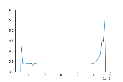
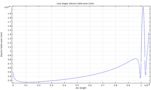
System in MD consists of two planes at an angle with respect to each other. Additionally, there is an adatom on the bottom plate at various positions. Tests showed that the greatest effect on the adatom happens when the adatom is near the edge, thus I will focus on that geometry. FEM calculations were conducted as to mimic the geometry and the dimensions of the MD system closely and as the adatom described as a hemisphere.
Electric field gradient comparisons
Echemdid simulation - pyramid - adatoms
Geometry :ca 80k atoms, truncated {111} pyramid in the middle, surrounded by adatoms. Simulation setup: cg minimization 1e-8 tolerance, 700 steps, box was allowed to relax. Velocity created at 10K, short equilibration with langevin thermostat, N-H barostat (fix nph). Then 10k steps raising temperature from 10K to 600K with langevin thermostat, while barostatting the box.
The results - stable system at 600K with 0 pressure in the x and y directions. Langevin thermostat performed better than the NH one, as that one was unstable for some reason.
